Microsoft Band 4 Light Sensor Repair

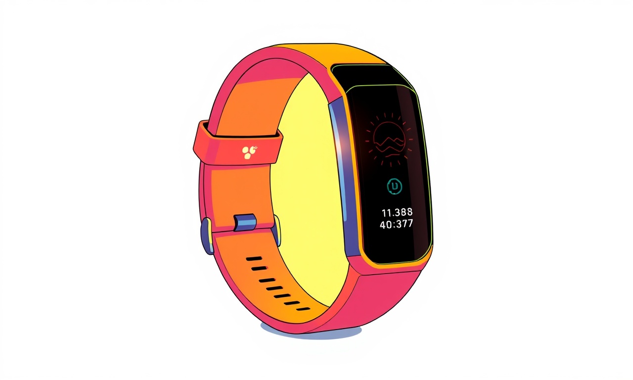
Welcome to this in‑depth guide focused on troubleshooting and fixing the light sensor on the Microsoft Band 4. This wearable device relies on its light sensor to calibrate screen brightness, detect ambient lighting for sleep monitoring, and enable other sensor‑driven features. When the sensor stops responding, the band may fail to adjust its display or record accurate light exposure data. While Microsoft no longer offers official repair services for the Band 4, the community has gathered a wealth of information on how to open the device, identify sensor faults, and replace the component if necessary.
Understanding the Light Sensor on the Microsoft Band 4
The light sensor in the Band 4 is a small photodiode array integrated into the device’s main PCB. It sits close to the display panel and feeds data to the microcontroller that governs the screen’s adaptive brightness. A malfunctioning sensor can manifest as a completely dim or over‑bright display, erroneous light exposure logs, or a failure to activate certain features that rely on ambient light detection.
Why the Sensor Matters
- Adaptive brightness: The Band 4 automatically dims or brightens the screen based on surrounding light levels. A faulty sensor prevents this adjustment, resulting in poor visibility or excessive battery drain.
- Sleep tracking: The sensor helps determine when the user is in a dark environment, aiding the device in identifying sleep periods. Without accurate light readings, sleep data may be unreliable.
- User experience: Many users prefer the Band 4’s automatic adjustment for comfort during daily wear. A broken sensor forces manual brightness changes, detracting from the seamless experience.
Signs That the Light Sensor Is Faulty
Before you open your Band 4, recognize the common symptoms that point to a light sensor problem:
- The screen stays at maximum brightness regardless of lighting conditions.
- The screen dims or brightens abruptly at random intervals, unrelated to ambient light changes.
- The “Ambient Light” section in the Band’s settings shows abnormal or static values.
- Sleep logs indicate inconsistent “low light” periods, even when the wearer sleeps in a dark room.
- The device reports an error related to the light sensor during diagnostics.
If you observe any of these issues, a sensor repair or replacement is likely needed.
Tools You Will Need
Gather the following before you begin. Having everything on hand will make the process smoother and reduce the risk of accidental damage.
- Miniature Phillips screwdriver (0.8 mm)
- Flat‑head pry tool or plastic opening tool
- Soldering iron with a fine tip (0.3 mm or less)
- Desoldering braid (see also our guide on Vuzix Mirage 3 audio jack fault fix)
- Solder paste or lead‑free solder
- Replacement light sensor module (compatible with Band 4)
- Tweezers
- Magnifying glass or microscope (optional, but helpful)
- Anti‑static wrist strap (recommended)
Preparing the Device
1. Power Down
Fully shut down the Band 4 and disconnect any cable. Let the battery rest for at least five minutes to discharge residual voltage. This minimizes the risk of short circuits while you work. (When charging or draining a battery, it’s a good idea to keep it within the same range as in the guide on Dell Spectron 1 battery calibration.)
2. Clean the Surface
Use a lint‑free cloth to wipe the exterior. Remove any adhesive residue or debris that may interfere with opening the case.
3. Identify the Opening Point
The Band 4’s back panel is held in place by a single screw at the bottom left. Locate it carefully; the screw is small, so use the miniature Phillips screwdriver.
Removing the Band 4
Step A: Unscrew the Back Cover
- Insert the screwdriver into the screw hole.
- Turn counter‑clockwise until the screw loosens and slides out.
- Keep the screw in a safe place—its size matters for reassembly.
Step B: Pry the Back Panel
- Insert the plastic opening tool between the edge of the back panel and the case frame.
- Gently lift the panel, working your way around the perimeter.
- Avoid using excessive force; the panel snaps off once all clips release.
Step C: Set Aside the Back Cover
- Place the back panel on a clean, flat surface, clip‑side up.
- Make a mental note of the orientation; this will help when you reassemble.
Accessing the Light Sensor
1. Locate the PCB
On the inside of the back panel, the main PCB sits snugly. The light sensor is a small rectangular component near the edge, close to the display.
2. Identify the Sensor
- It typically appears as a silver rectangle with a tiny black dot or a tiny black square on one corner.
- The sensor’s leads (usually two or three) connect it to the main circuit board via solder pads.
3. Examine the Connections
Using a magnifying glass or microscope, inspect the solder joints. Look for cracked, cold solder, or excessive solder that may indicate a fault. Also check for corrosion or discoloration, which can impede signal transmission.
Diagnosing the Issue
While visual inspection is valuable, you may want to verify the sensor’s functionality.
1. Test with a Multimeter
- Set your multimeter to the diode or continuity mode.
- Place the probes on each pair of solder pads on the sensor.
- A healthy sensor will show a consistent resistance or a small forward voltage drop.
If the readings are out of range, the sensor likely needs replacement.
2. Use a Soldering Iron for a Hot Swap
If you are comfortable with soldering, you can briefly heat the sensor’s leads and observe whether the device responds. This is more advanced and not recommended for beginners.
Replacing the Sensor
1. Desolder the Old Sensor
- Heat the solder joint with your soldering iron.
- Place the desoldering braid over the joint.
- Twist the braid to absorb the molten solder.
- Repeat for each lead until the sensor lifts cleanly from the board.
2. Clean the Pads
Use a small amount of cleaning solvent or isopropyl alcohol to remove leftover solder from the pads. Dry thoroughly.
3. Apply Solder Paste
- Using a fine tip, apply a small amount of solder paste to each pad.
- This ensures a smooth solder joint and reduces the risk of bridge faults.
4. Position the New Sensor
- Align the new sensor with the pads on the board.
- Hold it gently in place; the sensor should fit snugly without forcing.
5. Re‑solder the Leads
- Heat each joint carefully with the soldering iron.
- Add solder to achieve a shiny, conical joint.
- Inspect each connection; ensure no solder bridges.
6. Inspect the Board
Double‑check that no components have been displaced during the replacement. A misaligned component can cause additional issues.
Reassembling the Band 4
1. Place the Back Panel
- Align the panel with the PCB, ensuring all clips line up.
- Press gently to snap the panel back into place.
2. Reinstall the Screw
- Insert the screw into the bottom left hole.
- Tighten clockwise until snug, but avoid overtightening which can crack the case.
3. Verify Physical Integrity
Check that the band’s strap and display are intact. No visible gaps or misalignments should exist.
Testing the Fix
1. Power On the Device
Turn the Band 4 back on. If it boots normally, proceed to test the light sensor.
2. Adjust Ambient Light Settings
- Navigate to the settings menu.
- Enable the “Ambient Light” feature.
- Move the band from a bright environment into a darker room, then back again.
- Observe whether the screen brightness adjusts accordingly.
3. Record Light Exposure Data
- Open the sleep or health app.
- Monitor the light exposure log for correct readings during a simulated sleep cycle.
- A steady or properly scaled value indicates the sensor is functioning.
If the sensor still behaves erratically, revisit the soldering steps or consider the possibility of a damaged PCB.
Safety Tips and Common Pitfalls
- Avoid static: Use an anti‑static wrist strap to discharge static electricity that could damage the board.
- Use proper tools: A tiny screwdriver and fine‑tip soldering iron are essential. Rough tools can damage delicate components.
- Don’t overheat: Excessive heat can warp the PCB or melt nearby components. Keep the iron tip close but not too long.
- Keep the area clean: Solder residue or foreign objects can cause shorts. Use a clean, lint‑free cloth for any debris removal.
- Label the screw: Since the Band 4’s screw is small, it can be misplaced. Store it in a small container or magnetic tray.
When to Seek Professional Help
If you encounter any of the following, consider taking the device to a professional repair shop or a community repair group:
- PCB damage: Visible cracks, burnt traces, or discolored copper.
- Multiple component failures: The sensor isn’t the only fault.
- Inexperience with soldering: If you are new to electronics repair, a misstep can render the device unusable.
Final Thoughts
Repairing the light sensor on a Microsoft Band 4 is a doable task for those comfortable with delicate electronics. By following the steps outlined above, you can restore adaptive brightness, improve sleep tracking accuracy, and extend the life of your wearable. Though the Band 4 is an older device, many users still rely on its fitness and health features. A simple sensor replacement can bring it back to its former reliability.
Happy repairing, and enjoy the improved experience on your Band 4!
Discussion (10)
Join the Discussion
Your comment has been submitted for moderation.
Random Posts

Addressing Apple iPhone 14 Pro Max Battery Drain During Gaming Sessions
Learn why iPhone 14 Pro Max batteries drain during gaming, how to diagnose the issue, and practical tweaks to keep you playing longer with less power loss.
5 months ago

Curing iPhone 14 Plus Charging Port Wear After Daily Fast Charge Cycles
Fast charging can loosen your iPhone 14 Plus port. Learn to spot slow charging and loose cables, then fix it with simple home tricks or long, term prevention.
6 months ago
Xiaomi Mi SmartGlasses 3 Eye Tracking Error Fix
Fix the eye, tracking issue on Mi SmartGlasses 3 with this step, by, step guide to diagnose, clear errors, and restore functionality without repair.
1 year ago

Overcoming Sony X900H Color Saturation Drift During HDR Playback
Discover how to spot and fix color saturation drift on your Sony X900H during HDR playback, tune settings, correct HDR metadata, and keep your scenes vivid and natural.
4 months ago

Remediating Signal Dropout on Bowers & Wilkins PX8 Noise Cancelling Headphones
Discover why the Bowers & Wilkins PX8 may drop sound and how to fix it by tackling interference, low battery, outdated firmware, obstacles and Bluetooth settings for uninterrupted audio
1 week ago
Latest Posts

Fixing the Eufy RoboVac 15C Battery Drain Post Firmware Update
Fix the Eufy RoboVac 15C battery drain after firmware update with our quick guide: understand the changes, identify the cause, and follow step by step fixes to restore full runtime.
5 days ago

Solve Reolink Argus 3 Battery Drain When Using PIR Motion Sensor
Learn why the Argus 3 battery drains fast with the PIR sensor on and follow simple steps to fix it, extend runtime, and keep your camera ready without sacrificing motion detection.
5 days ago

Resolving Sound Distortion on Beats Studio3 Wireless Headphones
Learn how to pinpoint and fix common distortion in Beats Studio3 headphones from source issues to Bluetooth glitches so you can enjoy clear audio again.
6 days ago