Uncovering a Circuit Board Burnout on the DeLonghi DHF560 Portable Heater
Introduction
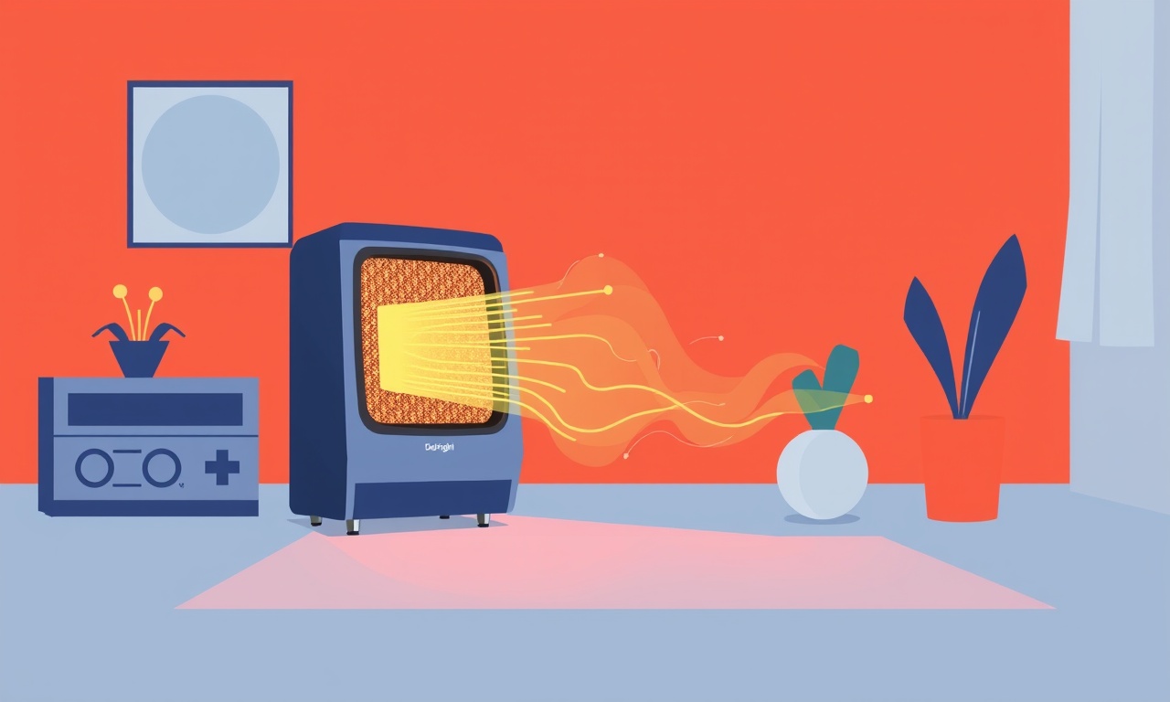
Winter evenings can feel endless when the heating system fails to keep up with the chill. The DeLonghi DHF560 portable heater is a popular choice for many households because of its compact size, rapid warm‑up time and safety features. Yet, like any electronic appliance, it can encounter internal faults that leave it silent and cold. One of the most frustrating and often misunderstood problems is a burned circuit board. When the heater stops turning on, producing heat, or intermittently shuts down, the culprit may be a damaged printed circuit board (PCB) that supplies power to the heating elements and control logic.
This guide walks you through everything you need to know to uncover, diagnose, and address a circuit board burnout on the DeLonghi DHF560. Whether you are a seasoned DIY enthusiast or a cautious homeowner, the step‑by‑step instructions, safety tips, and troubleshooting cues will help you restore the heater to reliable operation or decide when it is time to seek professional repair.
How the DHF560 Is Built
Before diving into fault detection, a brief overview of the heater’s internal layout is useful. The DHF560 consists of three primary sections:
- Power Input and Fuse Assembly – The cord plugs into a standard wall outlet, passes through a fuse holder, and feeds the main power transformer.
- Control PCB – A compact green board located behind the front panel houses the microcontroller, temperature sensor inputs, relays, and triacs that regulate voltage to the heating element. The board also contains the LED display driver and safety‑shutdown circuitry.
- Heating Element & Fan Assembly – The ceramic heating plate, wrapped in aluminum fins, is coupled with a rear‑mounted fan that pushes warm air out through the front grille.
The PCB is the brain of the unit. It monitors the thermostat setting, reads the ambient temperature, and modulates power to the heating element via a high‑current relay. Because the board handles large current spikes each time the heater turns on, it is exposed to heat, dust, and occasional voltage surges—all of which can lead to component failure.
Recognizing the Symptoms
A burned circuit board does not always manifest with dramatic smoke or a burning smell. The following signs are common indicators that the PCB may have been compromised:
- No Power On – The unit fails to light the LED display or fan when the power switch is engaged.
- Intermittent Operation – The heater turns off unexpectedly after a few minutes of heating, often accompanied by a flickering display.
- Error Codes – Some DHF560 models show a blinking “E” or display a “0” code when the internal safety circuit detects a fault.
- Unusual Odor – A faint, acrid smell reminiscent of melted plastic, especially after the heater has run for a short period.
- Warm or Hot PCB – Touching the exposed rear of the unit (when unplugged) reveals excessive warmth localized around the board area.
If you experience any combination of these symptoms, it is prudent to investigate the PCB before attempting to use the heater again. Continuing to operate a compromised unit can pose fire hazards and cause further damage.
Safety First
Working with electrical appliances carries inherent risks. Follow these precautions each time you open the DHF560:
- Unplug the Heater – Disconnect the power cord from the wall outlet and wait at least five minutes for residual charge to dissipate.
- Wear Protective Gear – Use insulated gloves and safety glasses to protect against sharp edges and accidental short circuits.
- Work in a Well‑Ventilated Area – If there is any lingering smoke or odor, ensure airflow to avoid inhaling potentially toxic fumes.
- Avoid Static Discharge – Ground yourself by touching a metal part of a grounded object before handling the PCB.
- Keep a Fire Extinguisher Nearby – Have a Class C fire extinguisher ready in case a component ignites during inspection.
Disassembling the DHF560
The heater’s design allows for relatively straightforward removal of the front panel and access to the internal components. Below is the disassembly procedure.
Removing the Front Grille
- Place the heater on a sturdy work surface with the front facing up.
- Locate the two plastic clips on each side of the grille. Gently pry them outward using a flat‑head screwdriver or a plastic pry tool.
- Once the clips are released, lift the grille away from the housing. Set it aside.
Detaching the Top Cover
- Behind the grille, you will see four Phillips screws securing the top cover. Remove all four screws and set them in a small container.
- Slide the top cover upward and pull it back to expose the internal circuitry and heating assembly.
Exposing the PCB
- The control board is mounted on a metal bracket attached to the bottom of the housing. It is typically secured with two more Phillips screws. Remove these screws.
- Carefully lift the PCB away from the bracket. You may notice a thin layer of dust or a faint discoloration on the board – this can be the first visual clue of overheating.
Disconnecting Wiring Connectors
- The board is linked to the heating element, fan motor, and temperature sensor via small plug‑in connectors. Press the release tabs and pull each connector straight out.
- Keep a reference photo or diagram of the connector arrangement for reassembly.
At this stage, the PCB is fully isolated and ready for inspection.
Visual Inspection of the Board
A burned PCB often shows distinct physical evidence. Examine the board under bright light and, if possible, a magnifying glass. Look for the following:
- Discolored Traces – Copper tracks that appear dark brown, black, or have a glossy sheen indicate overheating.
- Blown or Swollen Components – Capacitors may bulge, leak electrolyte, or show a cracked casing.
- Charred Resistors – Resistors with a blackened body or a faint smell of burnt resin are a clear sign of failure.
- Melted Solder Joints – Solder that has formed jagged, rounded beads rather than smooth, shiny seams.
- Burnt Diodes or Triacs – These power‑handling components can appear darkened or cracked.
If any of these signs are present, the board has likely suffered thermal damage and will need repair or replacement.
Testing the PCB with a Multimeter
Visual cues are helpful, but electrical testing provides definitive confirmation. You will need a digital multimeter capable of measuring continuity, resistance, and diode functionality.
Checking Continuity of Power Traces
- Set the multimeter to the continuity mode.
- Place one probe on the main power input pad (usually labeled “V+” or “L”) and the other on the corresponding output pad that feeds the heating element relay.
- A continuous beep indicates an intact trace. No beep suggests a broken line that may need solder bridging or board replacement.
Measuring Relay Coil Resistance
- Locate the relay coil terminals on the board.
- Switch the meter to resistance (Ω). A typical relay coil for this heater should read between 50 Ω and 150 Ω. Significantly higher resistance or an open circuit points to a faulty relay.
Verifying Diodes and Triacs
- Change the meter to diode test mode.
- Test each diode by placing the red probe on the anode and the black probe on the cathode; the meter should display a forward voltage (around 0.6 V). Reverse the probes – the meter should show “OL” (open loop). Any deviation suggests a damaged diode.
- For triacs, an ohmmeter reading should show low resistance in one direction (gate to MT1) and high resistance in the opposite direction. Inconsistent readings indicate a compromised triac.
Record all abnormal values. If multiple components fail the tests, it is usually more cost‑effective to replace the whole board.
Common Causes of PCB Burnout
Understanding why the board fails can help you prevent future occurrences. The DHF560’s PCB is prone to the following stressors:
- Voltage Surges – Sudden spikes from the mains supply, often caused by switching large appliances on or off, can overload the board’s protection circuits.
- Dust Accumulation – Over time, dust settles on the board and acts as an insulator, trapping heat. When the heater runs for extended periods, the temperature of the board can rise beyond safe limits.
- Insufficient Ventilation – The rear of the unit houses the fan and heating element. Blocking airflow with curtains or placing the heater too close to walls can cause internal temperatures to climb.
- Aging Components – Electrolytic capacitors lose their ability to filter voltage spikes as they age, making the board more vulnerable to surges.
- Mechanical Shock – Dropping or knocking the heater can fracture solder joints or micro‑cracks in the PCB traces.
Repair Options
Once you have confirmed a burnt PCB, you have three primary paths:
Replace the Entire PCB
- Pros – Guarantees that all damaged components are addressed. Minimal risk of overlooking a hidden fault.
- Cons – Requires sourcing a genuine replacement part, which may be costly or have limited availability.
To find a replacement, search for “DeLonghi DHF560 PCB” on authorized parts distributors or contact DeLonghi support. Verify the part number (often printed on the board) before purchase.
Re‑solder Burnt Traces
If the damage is limited to a few burned traces, you can repair them with a soldering iron and fine‑gauge solder.
- Clean the area with isopropyl alcohol.
- Use a fine tip to melt the damaged solder, removing any charred residue.
- Apply fresh solder to bridge the broken trace, ensuring a smooth, conductive path.
Replace Individual Components
When only certain components such as capacitors, resistors, or a triac are faulty, you can desolder the defective parts and solder in new equivalents.
- Match the exact voltage and amperage ratings.
- For electrolytic capacitors, note the polarity before installing the new part.
Component‑level repair is more time‑consuming but can be significantly cheaper than a full board replacement.
Reassembly Checklist
After repair or replacement, follow this checklist to ensure the heater is safely reassembled:
- All Connectors Re‑attached – Verify each plug is seated firmly and the release tabs click into place.
- Screws Securely Tightened – Use the original screws; avoid overtightening to prevent cracking the housing.
- Front Grille Properly Clipped – Ensure the clips engage fully so the grille does not detach during operation.
- Power Cord Clean – Inspect the cord for any cuts or fraying before plugging back in.
- Functional Test – Plug the heater into a GFCI‑protected outlet, set it to low, and observe the LED display, fan, and heating output for at least 5 minutes.
If any abnormal behavior occurs during the test, disconnect immediately and re‑inspect the board.
Preventive Maintenance
Even a newly repaired heater can fall victim to burnout if regular upkeep is ignored. Adopt these habits to extend the life of the DHF560:
- Clean Dust Quarterly – Unplug the unit, remove the front grille, and blow out dust with compressed air. Wipe the PCB surface gently with a lint‑free cloth.
- Use Surge Protectors – Plug the heater into a quality surge‑protecting power strip to buffer voltage spikes.
- Maintain Adequate Clearance – Keep at least 12 inches of space around the heater’s rear and sides to allow proper airflow.
- Avoid Continuous Full‑Power Operation – Cycle the heater on and off or use the thermostatic mode so the board does not stay under maximum load for extended periods.
- Inspect the Fuse Annually – A blown fuse can indicate power irregularities that may harm the PCB.
Following these steps dramatically reduces the likelihood of future circuit board failures.
When to Call a Professional
While many homeowners can successfully replace or repair a PCB, some scenarios merit professional assistance:
- Extensive Damage – If large sections of the board are charred or multiple components are burnt, a technician can assess whether a repair is feasible.
- Lack of Soldering Experience – Working with high‑current components without proper skill can create new hazards.
- Warranty Coverage – If the heater is still under manufacturer warranty, opening it may void the coverage. Contact DeLonghi support first.
- Unclear Diagnosis – If initial tests are inconclusive, a qualified service center can perform deeper diagnostics with specialized equipment.
Cost Considerations
Understanding the financial aspect helps you decide whether to repair or replace the heater.
| Option | Typical Cost (USD) | Pros | Cons |
|---|---|---|---|
| Full PCB Replacement | $80 – $150 (part only) + labor if not DIY | Restores original functionality | May be hard to find genuine part |
| Component‑Level Repair | $20 – $60 for parts | Cheapest if only a few parts fail | Requires soldering skill |
| Professional Repair | $120 – $200 (incl. labor) | Guarantee of proper work | Higher overall cost |
| New Heater Purchase | $100 – $180 for a new DHF560 | Brand‑new warranty | Full expense of new unit |
Weigh the age of your heater, the severity of damage, and your comfort level with electronics when making the decision.
Summary
A circuit board burnout is one of the most common failure modes in the DeLonghi DHF560 portable heater. By recognizing early symptoms, safely disassembling the unit, conducting a thorough visual and electrical inspection, and following a structured repair or replacement plan, you can bring the heater back to life or confidently decide to seek professional help. Regular maintenance, proper ventilation, and surge protection are essential habits that prevent future PCB failures and keep your heater delivering cozy warmth throughout the cold months.
Discussion (9)
Join the Discussion
Your comment has been submitted for moderation.
Random Posts
Reassessing the Audio Jack Dropout on LG Velvet 2
Explore why the LG Velvet 2's 3.5mm jack glitches, what triggers audio dropouts, user fixes, and LG's stance: essential insight for current and future Android phones.
1 year ago
Philips HP700 Fan Stalls Quietly Even At Low Speed Why This Happens And What To Do
Discover why your Philips HP700 quietly stalls at low speed, spot early signs, and fix the issue to keep steady airflow.
2 weeks ago

How to Stop Sharp LC-40M from Producing Audio Sync Issues While Gaming
Fix your Sharp LC-40M so game audio stays in sync. Learn quick settings tweaks, cable checks, and audio-output fixes that keep sound matching action for a flawless gaming experience.
6 months ago

Solve Arlo Pro 4 Wireless Connection Problems
Discover quick fixes for offline Arlo Pro 4 cameras. Check power, Wi, Fi, firmware, reset steps, and more get your live feed back up fast.
4 months ago
Panasonic D45 Dryer Timer Skips Final Drying Cycle
Discover why your Panasonic D45 dryer skips its final cycle, learn the symptoms, root causes, and easy fixes to keep clothes dry, save energy, and avoid extra runs.
5 months ago
Latest Posts

Fixing the Eufy RoboVac 15C Battery Drain Post Firmware Update
Fix the Eufy RoboVac 15C battery drain after firmware update with our quick guide: understand the changes, identify the cause, and follow step by step fixes to restore full runtime.
5 days ago

Solve Reolink Argus 3 Battery Drain When Using PIR Motion Sensor
Learn why the Argus 3 battery drains fast with the PIR sensor on and follow simple steps to fix it, extend runtime, and keep your camera ready without sacrificing motion detection.
5 days ago

Resolving Sound Distortion on Beats Studio3 Wireless Headphones
Learn how to pinpoint and fix common distortion in Beats Studio3 headphones from source issues to Bluetooth glitches so you can enjoy clear audio again.
6 days ago